Concrete BIM + VDC

Model the concrete.
Build from clarity.

Meier uses Revit and Autodesk Construction Cloud to coordinate structural concrete before installation—turning contract documents into field-ready information for planning, layout and execution.

StructuralArchitecturalCivilMEPTrade shops

Concrete models can carry through large, multi-level structures, below-grade work and the interfaces that shape field execution.

From model to field

Model. Drawings. Field.

Coordinated concrete geometry is translated into dimensioned working information for layout, forming and field coordination.

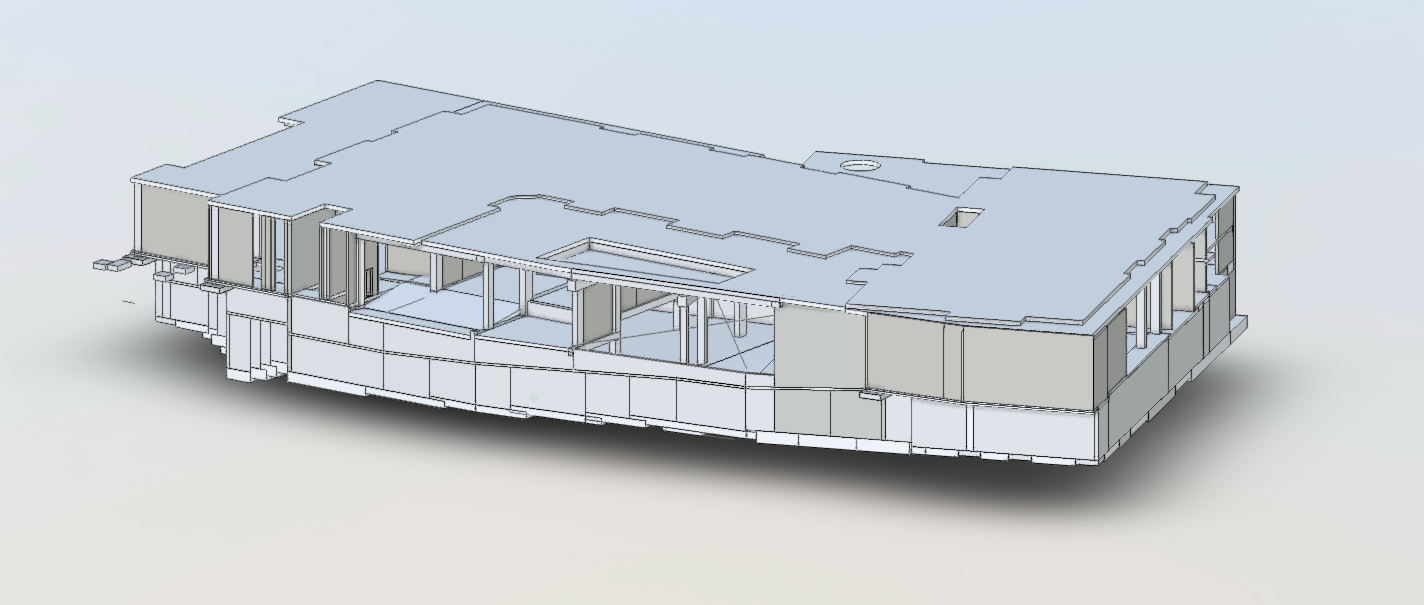
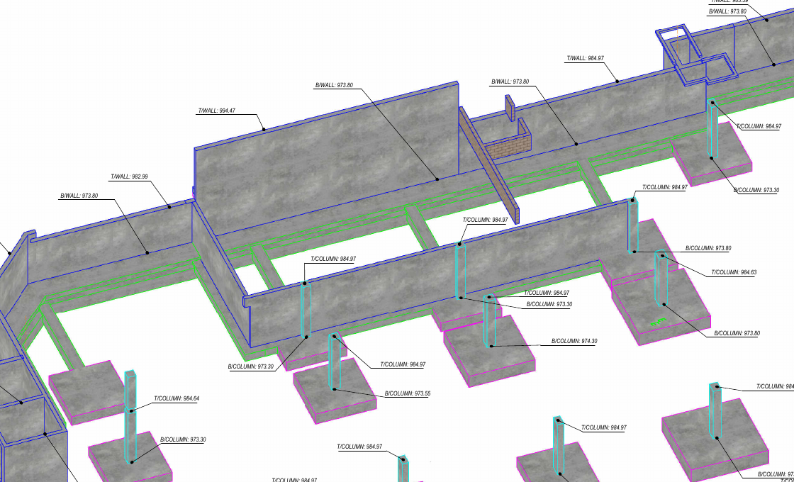
Concrete BIM model of the walls, columns and foundations in this project section01 / MODEL

Walls + columns in context

The model brings the concrete walls, columns and supporting foundations together in one view.

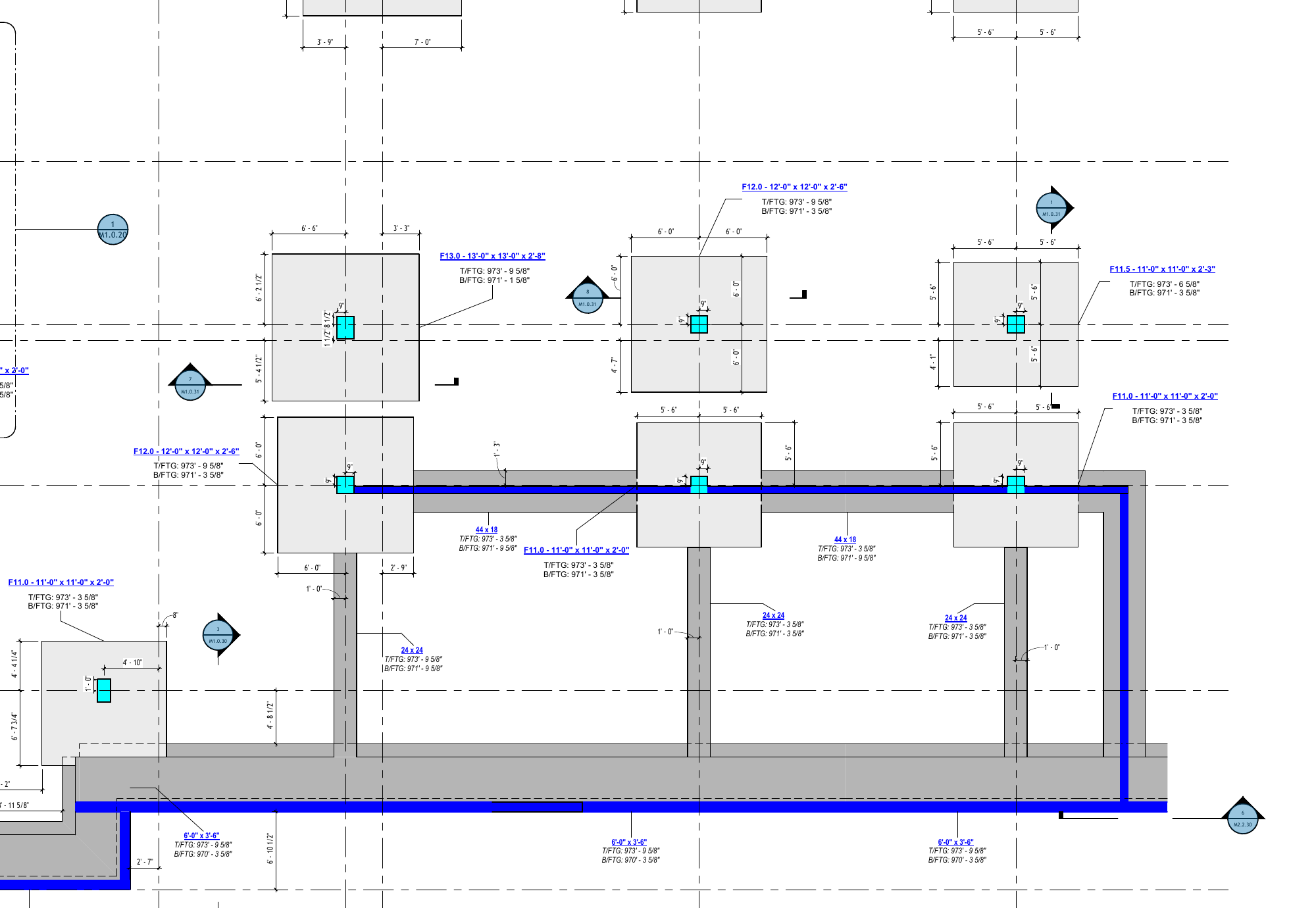
Enlarged crop from the Commons Lane foundation plan showing the full wall run, supporting footings, dimensions and top and bottom of footing elevations02 / WORKING DRAWING

The same section, dimensioned

The enlarged view keeps the wall, supporting footings, dimensions and top and bottom elevations readable.

View the full-page plan
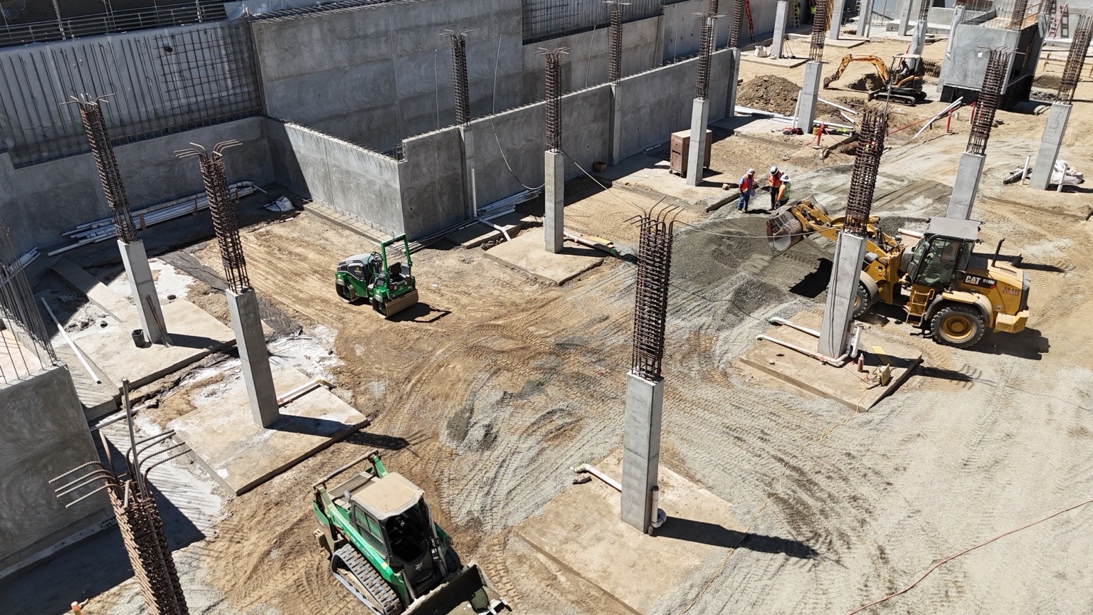
Aerial view of the matching concrete walls, columns and foundations during field execution03 / FIELD EXECUTION

Model to the work onsite

A field view of the same section shows how the coordinated geometry is taking shape.

Execution before installation

The model is not
the finished product.

The purpose of BIM/VDC is not to create a better rendering. It is to give the project team a clearer understanding of what must be built, where the interfaces occur and which questions need answers before they affect the field.

Meier models the structural concrete scope, compares information across the project documents and translates coordinated geometry into working drawings, RFIs, pour planning and current field information.

What we model

Concrete geometry.
Construction context.

Our models focus on the concrete elements and interfaces that influence formwork, layout, sequence and field execution. Reinforcing steel is coordinated as a trade interface rather than modeled as individual bars.

01

Foundations

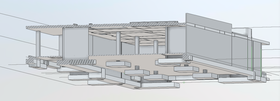
Footings, grade beams and mats modeled around structural loads, supporting conditions and construction sequence. Below-grade plumbing and electrical routing, slab elevations and adjacent conditions are compared to identify conflicts that may require coordinated foundation adjustments.

02

Vertical concrete

Cast-in-place walls and columns modeled by level with their openings, beam pockets, control joints and embed locations for stairs, elevators and structural-steel connections.

03

Slabs + decks

Slab-on-grade and elevated systems modeled with beams, curbs, thickened areas, depressions, soffit steps, slab edges and openings. PT profiles and reinforcing requirements are reviewed where they influence concrete geometry and coordination.

04

Interfaces

Embeds, blockouts, sleeves, pits, penetrations and perimeter conditions coordinated against architectural, civil and MEP information, along with shoring, elevator, stair, structural-steel, embed and other applicable trade shop drawings.
Coordination workflow

One model.
Multiple document sets.

Structural information does not exist in isolation. Meier compares the documents that affect the concrete package and escalates unresolved conditions through the project's formal coordination process.

01

Build

Develop the concrete model from the current contract documents and approved project information.

02

Compare

Review structural geometry against the current architectural, civil, MEP and trade-shop information that affects the concrete.

03

Coordinate

Identify conflicts, missing dimensions, elevation differences and penetrations; share relevant information with affected trades and route requested changes for AOR or SEOR approval when required.

04

Review

Check the model and working drawings against current documents, approved RFIs, submittals and constructability requirements before release.

05

Publish

Issue coordinated views, working drawings and current approved model information through Autodesk Construction Cloud.

Information reviewed throughout the workflow

StructuralArchitecturalCivilMEPTrade shops

From model to field

Information built
for the work ahead.

The value of the model is measured by the decisions it improves and the uncertainty it removes from upcoming work.

01

Field working drawings

Gridline dimensions, top-of-foundation information, finished-floor and soffit elevations, openings, embeds and concrete geometry organized for field use.

02

Constructability + RFIs

Clear graphics that isolate conflicts and unanswered conditions so the project team can resolve them before they reach installation.

03

Pour planning

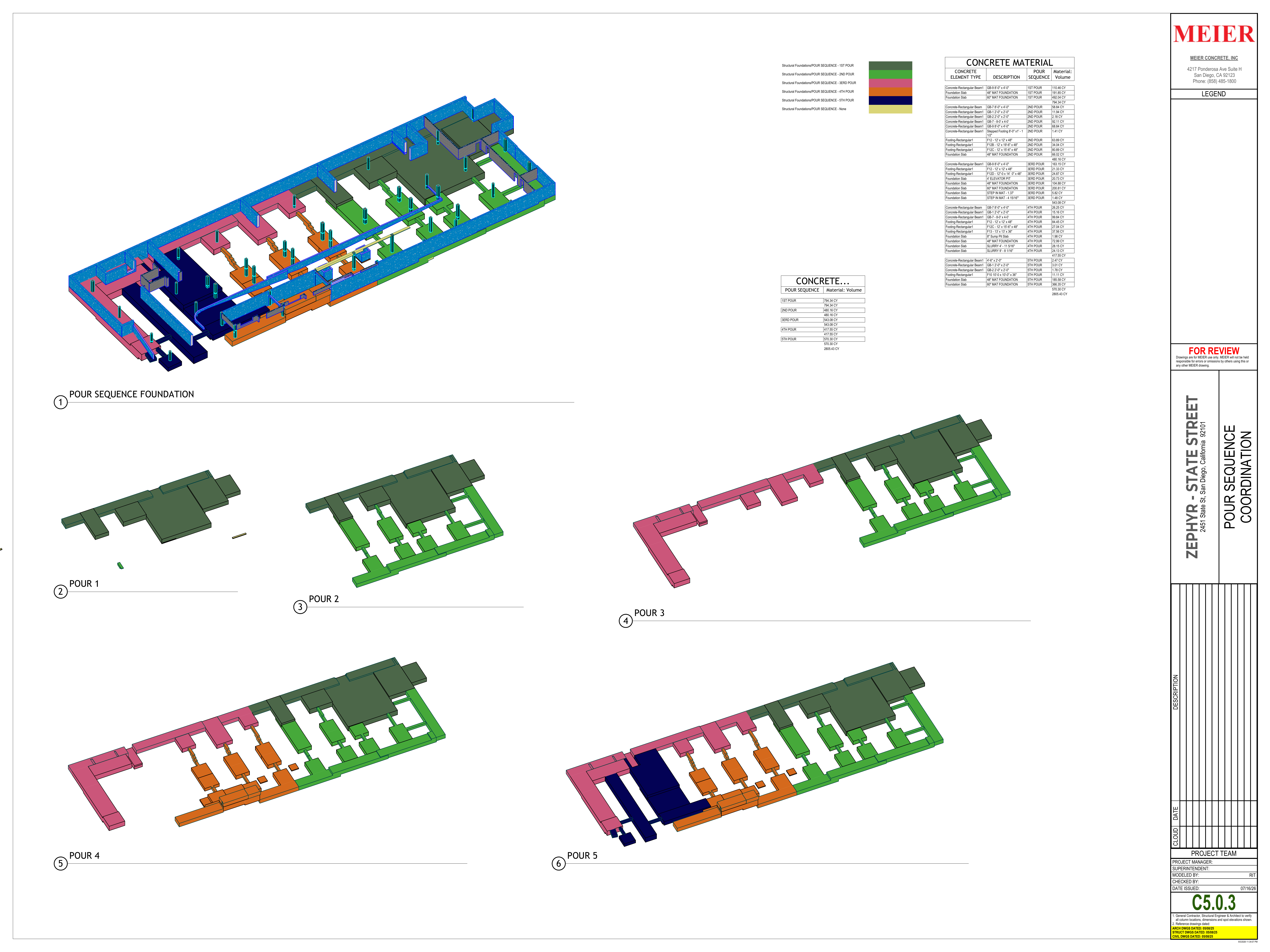
Models organized by level and pour section to support sequence, access, shoring strategy and upcoming-pour preparation.

04

Quantity visibility

Model-based concrete quantities provide additional visibility for scope validation, procurement, pour planning and near-term field decisions.

Review + accountability

Model production
with field judgment.

Accuracy depends on more than software. Meier uses layered review so the model reflects current contract documents, approved information, project conditions and the coordinated field plan.

01

VDC production

Build and maintain the concrete model, working views and revision history.

02

Project engineering

Review constructability and accuracy against the current contract documents and field plan.

03

Quality review

Check critical dimensions, elevations, openings, interfaces and published deliverables before field use.

04

Field constructability

Superintendents and project teams identify constructability concerns before work proceeds. Questions are resolved through the appropriate approval process, the model is updated when required and current information is reissued for construction.

MODELED IN

REVIT

COORDINATED + PUBLISHED THROUGH

AUTODESK CONSTRUCTION CLOUD

Have a project to build?

Bring us in early.

Start a conversation ↗